irrigation check valve
dismantling joint
tek control
air pressure valve
triple offset butterfly valve
In fluid and gas control systems, pressure control valves and flow control valves are fundamental components designed to manage the movement and force of fluid or air. While they both contribute to the overall efficiency of a system, their roles and functionalities differ significantly.
What Are Flow Control Valves?
The flow control valves are used for controlling and adjusting the fluid or gas flow through the system.
The flow control valve (FCV) is exactly the same except it gets its signals from a flow transmitter (FT). Just like the PT, an FT is basically a flow meter that is able to communicate with a related valve. Again, like the PCV, the FCV opens or closes based on the required flow and the signals it receives from the FT.
What Are Pressure Control Valves?
The pressure control valve is used to regulate the pressure of a fluid passing through the pipe.
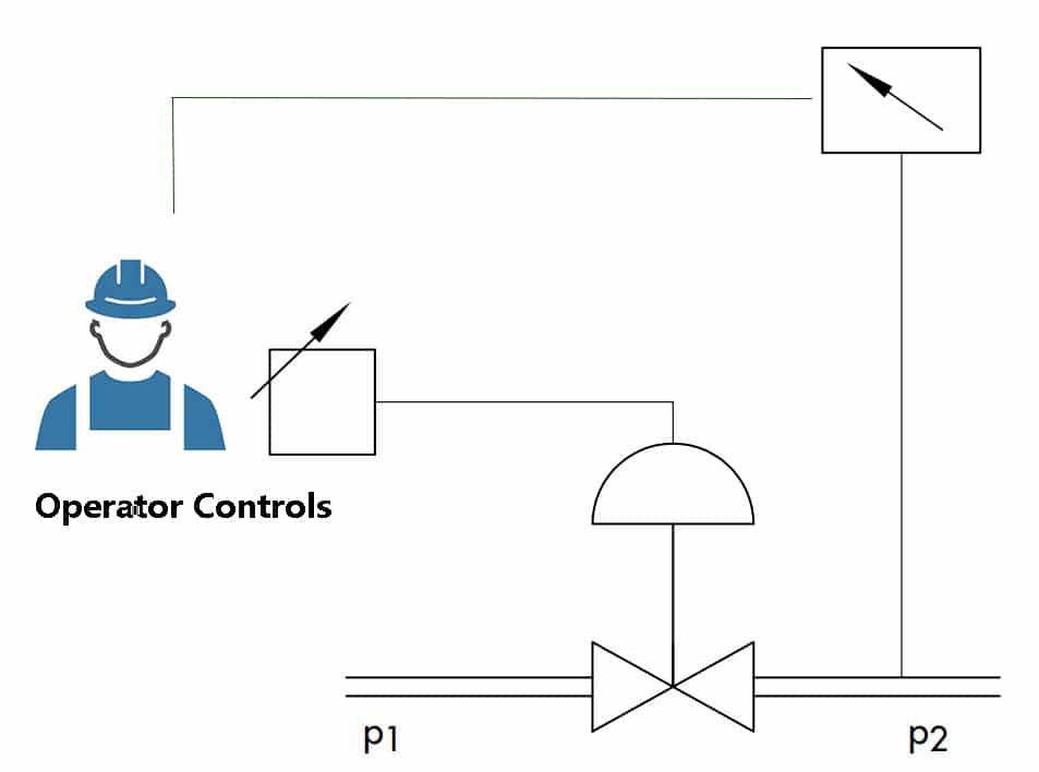
A pressure control valve (PCV) opens and closes based on the setpoint predetermined by an engineer. This is usually controlled using a pressure transmitter (PT). The PT is basically an electronic pressure gauge that sends signals to the PCV and tells it whether or not there is enough pressure entering the equipment and the PCV opens or closes to compensate.
Ultimately, pressure and flow are not independent characteristics of fluid transport. You can’t change one without changing the other. But what you can do is monitor and control one, subjugating the other to follow. Pressure and flow control valves can look almost indistinguishable sometimes, except for the sensing mechanism, which is monitoring the variable you need in controlling.
A pressure control valve opens and closes depending on the setpoint foreordained by a specialist. This is normally controlled utilizing a pressure transmitter. The flow control valve is actually the equivalent with the exception of it getting its signs from a flow transmitter. Much the same as the pressure transmitter, a flow transmitter is essentially a flow meter that can interact with a related valve.
In essence, while pressure control valves safeguard system integrity by managing pressure, flow control valves ensure operational precision by controlling the rate of fluid or air flow. Both types of valves play crucial roles in diverse applications, contributing to the safety, efficiency, and sustainability of numerous systems.
Pressure Control Valve Vs. Flow Control Valve
So the choice between a pressure control valve and a flow control valve depends on the specific application requirements, with pressure control valves used to maintain a constant pressure and flow control valves used to regulate the volume of fluid/gas passing through a system over a specific period.
Pressure Control Valves V.S Pressure Regulators
What is the difference between a pneumatic control valve and a self-operated control valve?
Does A Pressure Regulator Affect Flow?
Indeed, a pressure regulator plays a significant role in managing the flow of a fluid or gas through a system, directly affecting the flow rate. This is particularly pertinent in systems that require low flow rates for optimal performance.
Flow control at low flow rates can be a challenging endeavor. Precise control over the volume and speed of fluid or gas is required to ensure the system functions optimally. A great solution to this challenge is the use of an adjustable water flow restrictor. These devices enable the user to manually set the desired flow rate, maintaining the necessary pressure in the system.
In addition to water systems, air systems, such as HVAC units, also require precise control of flow rates. The introduction of a digital airflow control valve into these systems brings about a level of accuracy and automation that was previously hard to achieve. These digital valves can monitor and adjust the flow of air in real-time, greatly enhancing the overall efficiency of the system.
In fluid control systems, various components work together to regulate the flow and pressure of liquids and gases. To ensure optimal performance and efficiency, it is essential to understand the functions of these components, such as pressure flow controllers, back pressure regulators for slurries, downstream pressure controllers, e/p pressure regulators, pressure drop, valve body, flow path, and check valves.
Pressure Flow Controller
A pressure flow controller is a device that maintains a constant pressure in a system by automatically adjusting the flow rate. This helps to stabilize the pressure, ensuring consistent and reliable operation.
Back Pressure Regulator for Slurries
Designed to handle abrasive and corrosive materials, a back pressure regulator for slurries is a specialized type of pressure control valve. It maintains a desired upstream pressure by regulating the flow of slurries in processing plants, such as those found in the mining and chemical industries.
Downstream Pressure Controllers
Downstream pressure controllers are used to protect sensitive equipment from pressure fluctuations or to maintain a specific pressure in a process. These types of pressure control valves adjust the flow rate to maintain a constant pressure level downstream of the valve.
E/P Pressure Regulator
An e/p pressure regulator, or electro-pneumatic pressure regulator, uses an electrical input to control the pressure of compressed air or gas. This type of regulator is commonly found in industrial automation systems and provides precise pressure control for various applications.
Pressure Drop
Pressure drop refers to the decrease in pressure as a fluid flows through a system. This can be caused by factors such as friction, changes in flow path, or restrictions in the system. Understanding pressure drop is crucial for designing efficient fluid control systems and selecting the appropriate components.
Valve Body
The valve body is the primary component of a valve, housing its internal parts and providing a flow path for the fluid. The design of the valve body affects the valve’s performance, including its flow capacity and pressure drop characteristics.
Flow Path
The flow path is the route that a fluid takes as it moves through a system. It is determined by the arrangement of components, such as pipes, valves, and fittings. A well-designed flow path ensures smooth and efficient fluid flow, minimizing pressure drop and energy loss.
Check Valve
A check valve is a type of flow control valve that allows fluid to flow in one direction only, preventing reverse flow. Check valves are essential for protecting pumps and other equipment from damage caused by backflow, ensuring the safe and reliable operation of fluid systems.
How to Adjust Pressure Control Valves?
During the installation of pressure control valves, the engineers need to adjust control valves on-site. This is a significant step for commissioning. So we need to understand the various parts of the mechanical positioner and the working principle of the mechanical positioner. The following words will tell you all about the information on adjusting control valves.
Selecting the right components is essential when choosing a pressure control system for any industrial or commercial application. One crucial element of such a system is the air flow control 6 feedback circuit, which ensures stable and accurate regulation of air flow. While it might be tempting to opt for a cheap flow control valve, it’s important to prioritize quality and reliability to avoid potential issues down the line.
Top Mistake to Avoid While Installation Control Valves
In many applications, a compressed air flow control valve is used to manage the flow of compressed air accurately and efficiently. This component can be found in systems that utilize a mode door actuator or a mode actuator to control the direction of air flow within an HVAC system. The integration of automatic climate control features further enhances the overall performance and user experience, providing a comfortable environment in various settings.
Lastly, safety should never be overlooked when designing a pressure control system. A key component to consider is the HVAC B fuse, which protects the system from electrical faults and potential damage. By carefully selecting the right components and prioritizing quality, you can create an effective and reliable pressure control system that meets your specific requirements.
Parts of Linear Mechanical Positioner for Globe Control Valve
Principle of Linear E/P Positioner (ex. YT-1000L made by ROTORK/YTC)
When INPUT SIGNAL is supplied to the positioner to open the valve, power is generated
from ① the torque motor and pushes ② the flapper to the opposite side of ③ the nozzle.
The gap between ③ the nozzle and ② the flapper becomes wider and from the inner part of ④
the pilot left to ⑤ the spool, air inside ⑨ the chamber is exhausted through ③ the nozzle.
Due to this effect ⑤ the spool moves to the right. Then, ⑦ the seat which was blocked by
⑧ the poppet pushes the poppet away and supplied pressure (air) goes through ⑦ the seat
and OUT1 Port and enters into ⑩ the chamber of the actuator. Then ⑩ chamber’s pressure
will increase and when there is enough pressure inside the chamber to push the actuator’s
⑪ spring, the actuator’s ⑫ stem will start to go down and through the feedback lever, the stem’s
linear motion will be converted to span ⑭ lever’s rotary motion. This span ⑭ lever’s rotary
motion will then once again rotate ⑮ the span and pull the spring. When the valve’s
position reaches the given input signal, the span ⑯ spring’s pulling force and ① torque motor’s
power will be balanced and move ② the flapper back to its original position to reduce the gap
between ③ the nozzle. The amount of air being exhausted through ③ the nozzle will reduce
and left to ⑤ the spool ⑨ the chamber pressure will increase again. ⑤ Spool will move
back to its original position on the left and ⑧ the poppet will also move in the same direction
blocking ⑦ the seat to stop the air coming into the ⑩ chamber through the SUPPLY. As a
result, the actuator will stop operating and the positioner will return to its normal condition.
Wiring Diagram of Valve Positioner
Linear Positioner Installation
Pneumatic globe type pressure control valve usually assembles linear positioner for diaphragm actuator or piston actuator.
Step 1: Please refer to the above wiring diagram of the electro-pneumatic positioner to connect power cables to the terminal.
Step 2: Check the positioner’s feedback lever position, it should be vertical to the valve stem at 50% of the valve stroke, same as the following picture.
Step 3: Connect air power to the diaphragm actuator, usually, it’s 2.4 bar, then send a 4mA input signal to see if the valve is closed, and 20mA signal valve is fully open. (Failure position valve close, air to open) When we set zero and endpoints positions are set, then the rest of the position will be automatically calibrated. (25%, 50%, 75% position)
If you want to know more about installation problems that happened on-site when you are commissioning or maintenance you can read the below post.
What is the failure position of the control valves and how to solve it?
Pressure Regulator Vs Flow Regulator
A pressure regulator and a flow regulator are both types of valves that control fluid flow, but they operate based on different principles. A pressure regulator is a valve that is designed to maintain a constant pressure downstream, regardless of fluctuations in the inlet pressure. It helps to regulate the pressure of a fluid as it passes through a system.
On the other hand, a flow regulator is a valve that is designed to maintain a constant fluid flow rate, regardless of fluctuations in pressure. It helps to regulate the rate of flow of a fluid through a system.
Pressure Regulator Vs Flow Control Valve
The main difference between a pressure regulator and a flow control valve is their focus. Pressure regulators are focused on maintaining constant pressure, whereas flow control valves are focused on maintaining a constant flow rate. The choice between them depends on the specific requirements of the system in question, such as the desired flow rate or the maximum operating pressure.
Flow Control Vs Pressure Control
Pressure control is achieved through the use of pressure control valves that can control fluid/gas pressure by restricting or increasing the flow rate. These valves help to maintain constant pressure inside the pipeline or system.
The choice between flow and pressure control depends on the application objectives, system requirements, and industry standards. For example, if the objective is to maintain a steady flow rate, then flow control valves would be the best option. However, if the objective is to maintain constant pressure, then pressure control valves would be more appropriate.
The pneumatic pressure relief valve symbol is widely recognized in technical schematics for controlling the pressure in fluid systems.
Industrial Valve Symbols
Valve Actuator Symbols
Control Valve Symbols by Function
Common Valve Symbols
We provide various industrial valve symbols, including ball valves, gate valves, check valves, plug valves, diaphragm valves, safety valves, pressure regulators, solenoid valves, butterfly valves, and control valves. In case you will need it during the engineering fluid process. An air pressure regulating valve is an essential part of many industrial processes, as it maintains the desired pressure within pneumatic systems.
Pressure Control Valve Symbol
Self Actuated Pressure Control Valve Manufacturers
Self-actuated pressure control valves are used to keep the adjustable set-point pressure within a certain range in tanks or processes. It doesn’t request any auxiliary energy to operate valves but by the medium energy itself. Automatic flow regulating valves are used in various industries to control the rate of flow in a fluid system automatically
Since the self-acting pressure control valves do not need air supply or electric power to operate, so it’s kind of the most cost-effective pressure control valves to achieve a simple process of pressure control.
Back pressure control valve definition refers to a device designed to maintain a set pressure upstream of itself at its inlet. Air pressure regulators are integral in many industrial and commercial applications, reducing input pressure to a steady and manageable output pressure. The output pressure refers to the pressure coming out of a system, device, or material, which is often regulated for optimal system performance. A filter in a fluid system serves to remove contaminants and particulates, promoting longer system life and improved performance.
Final Thoughts
Learn from this post, you already know the difference between a flow control valve and a pressure control valve. For improved fluid control in your hydraulic system, you might want to buy a flow control valve from a reputable supplier. THINKTANK is a reliable control valve manufacturer who experiencing over 30 years in manufacturing control valves. So if you have any questions, just feel free to contact us. Also, you can read more posts about control valves below.
Control Valves 101: Valve Types, Applications, Components, and Accessories
Control Valves in the Textile Mills
Dynamic Application and Analysis of Control Valve Pressure Recovery Coefficient FL in Engineering Design
Control Valves with Valve Positioner
Which Data Should Be Considered When We Calculate and Select Control Valves?