chevy 350 valve covers
lt4 valve covers
ford 460 valve covers
The control valve is equipment or system that regulator the capacity of air, water, steam, or other liquid. The main function of the control valve is to modulate the gas or liquid, the valve can be open or close, or open at any travel position.
We know that the common control valves can be divided into two kinds of pneumatic and electric control valves, for different actuation types, the controller is also different. Due to the control valve can’t open or close by itself, so we need a controller to send a signal to the valve actuator, valve positioner, or pilot to control the valve opening.
1. Pneumatic control valves
A pneumatic actuated control valves use a pneumatic pilot as a controller, and the valve mechanical positioner, or digital/smart positioner received the signal from the controller.
Control Valves 101: Valve Types, Applications, Components, and Accessories
2. Electric control valves
Electric actuated control valves use an eclectic pilot as a controller, it can be a programmable logic controller or remote terminal unit.
How does a pressure valve controller work?
It is important to point out that not all control systems need a controller. For example, an on-off valve and actuator can be operated directly from a thermostat. The operation of high limit safety controls can be used to close valves or switch off fuel supplies.
How to quickly understand various industrial valve types and their applications?
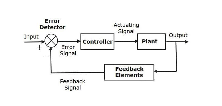
So a controller is needed when the control applications requirements become more advanced and complex. The controller gets a feedback signal from the processing, compare it with the variable parameter and the desired data, then decides to send a signal to operate the valve action.
Pneumatic controllers were popular controllers a decade ago, but now they use usually refers to situations in hazardous areas where the risk of an electrical or electronic explosion is ruled out in order to use a pneumatic controller, so not only is it safe to use a pneumatic controller, but it costs less than most of the popular electronic digital, or microprocessor controllers available today.
3 Typical Systems of Steam Pressure Reducing Station
The functions carried out by the controller can be very complex and it is beyond the scope of this publication to explain how they work. There are a number of major variations that need to be considered, we just list the major variations for your reference.
1. Pressure valve controller for single-loop
A single-loop controller is used to operate one valve/actuator from a single sensor.
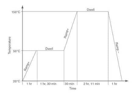
A single loop controller has the ability to perform ramp and dwell functions. It may have a typical multi-sequence pattern like the one shown as blow. In this figure a series of ramps (temperature change) and dwell functions (maintaining temperature) were carried out over a period of time.
6 Typical Applications of Fusible Link Valves and How Does It Work?
Typical multi-sequence ramp and dwell pattern
2. Control valve controller for multi-loop
A multi-loop controller has the ability to operate more than one valve/actuator from more than one sensor.
Frequently Asked Questions About Globe Valves
3. Single Signal
The single signal means the controller only accepts one signal from the sensor and sends it to the actuator.
4. Multi-Signal
The multi-signal means the controller can receive multiple signals from the sensor and sends them to the actuator.
5. Real-time
Real-time may include a time clock to switch at pre-determined, pre-set times.
Control Valves Are Used in The 4 Main Systems of The Power Station
6. Elapsed time
Elapsed time means before or after other items of plant are switched on or off, it may switch at a pre-set time.
7. Sensors and Transducers
A wide variety of sensors and transmitters are required in control systems to monitor pressure, temperature, liquid level, or other physical characteristics. Sensors are a very important part of the control system, through which changes in the controlled variable are sensed.
Small changes in resistance emitted by a sensor in response to a change in temperature may be converted to voltage or current for onward transmission to the controller. That is, the signal from the sensor may be so small that it can be adjusted and amplified locally by a change in temperature that causes a change in voltage, or possibly a change in resistance, for effective reading.
Due to the resistance generated by the wiring and the effects of electrical interference, there will be some deviation in the transmission process.
8. Liquid-filled and gas-filled system sensors or pressure system
The filled system sensors are used with pneumatic controllers. The term ‘Programmable Logic Controller (PLC)’ is frequently used in control literature. In a process, the controller must initiate a sequence of actions, such as turning valves or pumps on or off. In some conditions, the whole sequence is on a timed basis but often the various steps may be triggered by a specific condition being reached and maintained for a certain time period. For example, A vessel is filled or a certain temperature is reached. The process can be controlled by a PLC that uses a standard interface for actuators and sensors.
The mill room controller is another complex controller type, generally, it may be used to control the pump, heating control valve, boiler, or other equipment.
The filling medium used mercury in the past years, but due to health and safety problems, now uses inert gas in the filled sensor system, such as nitrogen gas. When the temperature increases, the filled fluid expands and causes the Bourdon tube to uncoil; when the temperature decreases, the filled fluid contracts, and causes the Bourdon tube to coil more tightly. This coil motion is used to operate the levers within the pneumatic controller, allowing it to accomplish its task. The pressure-sensing version will typically use simply a pressure tube connected to the Bourdon tubing.
9. RTDs(Resistance temperature detectors)
RTDs play a role like electrical transducers that convert temperature alters to changes in electrical resistance. As the temperature changes, the electrical resistance of certain metals changes too. The following figure shows the relationship between resistance and temperature for the Pt100 sensor. (Nickel, platinum, and copper are the metals that meet resistance temperature detectors requirements)
The change in resistance from 0C to 100C is specified by the resistance temperature detector. Platinum RTDs are used the most for typical applications. Pt 100 sensors are constructed with a resistance of 100 ohms at 0°C, and with high accuracy between 0°~100°C when they can be used over a temperature range of -200°C to +800°C. According to the resistance and temperature chart, the resistance increases almost linearly with temperature, the Pt100 has a relatively small change in resistance, which needs to be carefully measured. The resistance in the connection cable needs to be properly compensated.
10. Thermistors
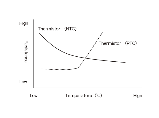
Thermistors use a semiconductor material whose resistance varies greatly with increasing temperature but is nonlinear. The resistance decreases with increasing temperature(NTC-negative coefficient thermistor).
PTC Positive coefficient thermistors can be made if the resistance increases with rising temperature, but their response curve makes them unsuitable for temperature detection.
Thermistors are less complex and less expensive than RTDs, but they do not have the same accuracy and repeatability. The resistance of the connecting cable is unimportant because of its high resistance.
Thermistors do not have the same high accuracy and repeatability that RTDs do, but its less complex and less expensive. Their high resistance means that the resistance of the connecting cable is less important.
11. Thermocouples
We all know that any pair of different metals can be used to make thermocouples, but the common standard types are J-type, K-type, T-type, and others. Of these, the most widely used general purpose thermocouple is type K.
The dissimilar metals used in type K thermocouples are chromium (90% nickel, 10% chromium) and aluminum (94% nickel, 3% manganese, 2% aluminum and 1% silicon) and can be used in the range of 0°C to 1260°C. For the material of the extension tails, it is possible to make the same material as the thermocouple itself wire, also
It may also be a compensation cable made of copper and copper-nickel alloy. It is important to note that both extension wires must be of the same material.
There are a wide variety of sizes and shapes of thermocouples. Over a wide temperature range, they are affordable, rugged, and quite accurate. However, the reference junction temperature must be kept at a constant value, otherwise, the deviation has to compensate for. Low junction voltages mean that special shielded cables and careful installation must be used to prevent electrical interference or “noise” from distorting the signal.
12. Digital addressing
Digital addressing allows the controller to send messages over a set of wires that have several receivers attached to them but are only able to communicate with one of them if needed. This is accomplished by assigning an address to each receiver, which the controller must first broadcast.
There are there common digital addressing in the control system, HART, PROFIBUS Fieldbus(PF), and Foundation™ Fieldbus(FF).
What is HART communication protocol?
HART communication protocol, which stands for Highway Addressable Remote Transducer, is a standard originally developed as a communication protocol for controlling field devices that operate on a 4-20 mA control signal. HART® is an industry standard for defining communication protocols between control systems and intelligent field devices. The most widely used digital communication protocol in the process industries is HART®. Here are some reasons:
- All of the major suppliers of process field instruments are supported by HART® communication protocol.
- 4-20 mA signals are allowed to co-exist with digital communication on existing 2-wire loops to preserve existing control strategies.
- It is compatible with analog devices.
- HART® communication protocol supplies some valuable information for installation and maintenance, such as product information, range and span data, measured values, Tag-IDs, and diagnostics.
- The use of multidrop networks can support the savings of the cabling.
- Improved management and use of smart instrument networks reduce operating costs.
What is PROFIBUS Fieldbus(PF) communication protocol?
Because PROFIBUS® is an open Fieldbus standard, it is manufacturer-independent and therefore has a wide range of applications in manufacturing and process automation. Any special interface adjustment can be required to communicate between devices of different manufacturers.
PROFIBUS® is suitable both for high-speed, time-critical applications and for complex communication tasks. It supplies functionally graded communication protocols DP and FMS. depending on the application, transmission technologies can be used such as RS-485, IEC 1158-2, or fiber optics.
PROFIBUS® defines the technical characteristics of a serial Fieldbus® system with which distributed digital programmable controllers can be networked from the field level to the unit level. PROFIBUS® is a multi-master system and thus allows several automation, engineering, or visualization systems to operate jointly with their peripheral devices distributed on a single bus.
What is Foundation™ Fieldbus(FF) communication protocol?
The Foundation™ Fieldbus communication protocol is an entirely digital, serial, bi-directional communication system that serves as a local area network (LAN) for plant instrumentation and control facilities. The Fieldbus® environment is the foundation-level digital network group in the plant network hierarchy. Foundation™ Fieldbus is used for both process and manufacturing automation applications and has the built-in capability to distribute control applications over the network.
13. Interoperability
Foundation™ Fieldbus provides interoperability, a Fieldbus® device can be interchanged by similar devices with additional features from different vendors on the same Fieldbus® network, while keeping the specified operation. This allows users to “mix and match” field devices and host systems from different suppliers. Individual Fieldbus® devices can also communicate and receive multivariate data and transmit them directly to each other via a common Fieldbus®, allowing new devices to be added to the Fieldbus® without interruption of service.
Valves and Regulators Used for Tank Blanketing System – Tank Pressure Control